Manage Access Points
The Manage Access Points window on the Analytics page shows all access points for the selected project on the Projects panel.
To open the Manage Access Points window, click on the button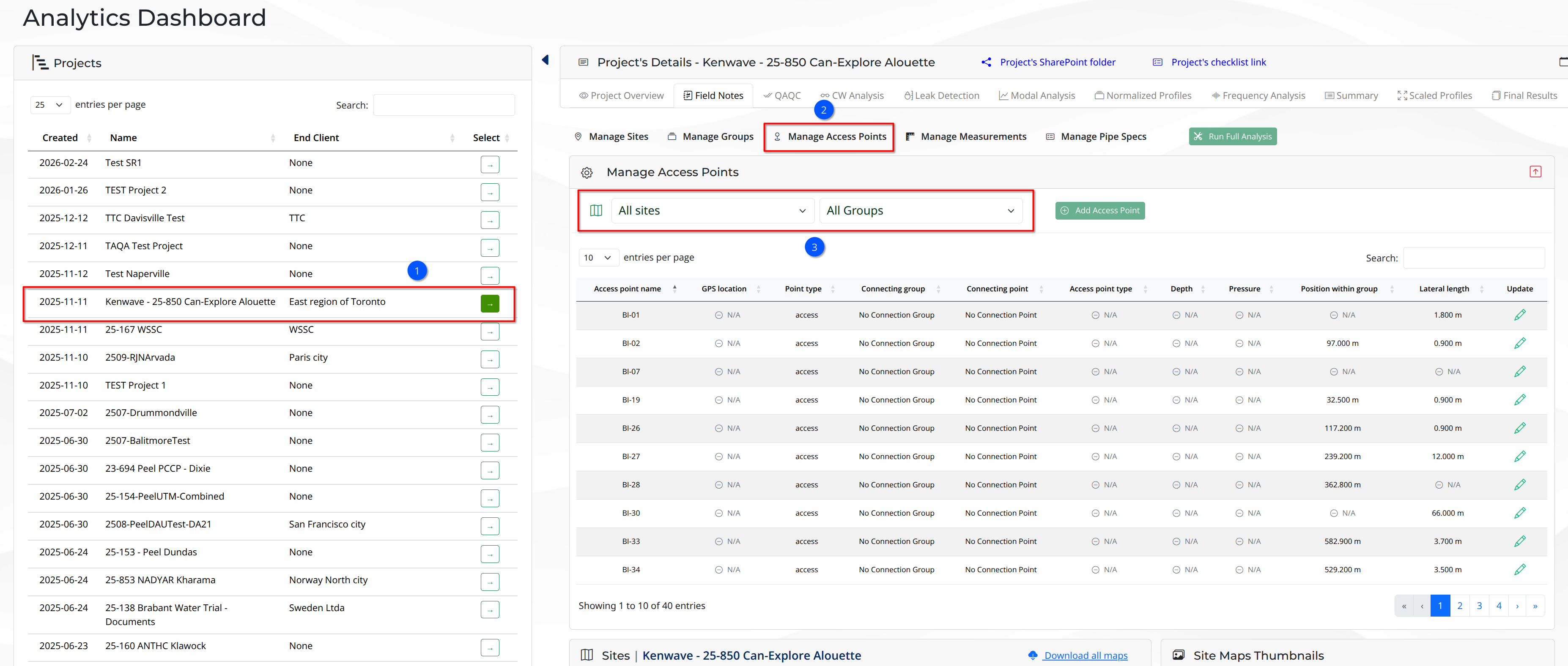
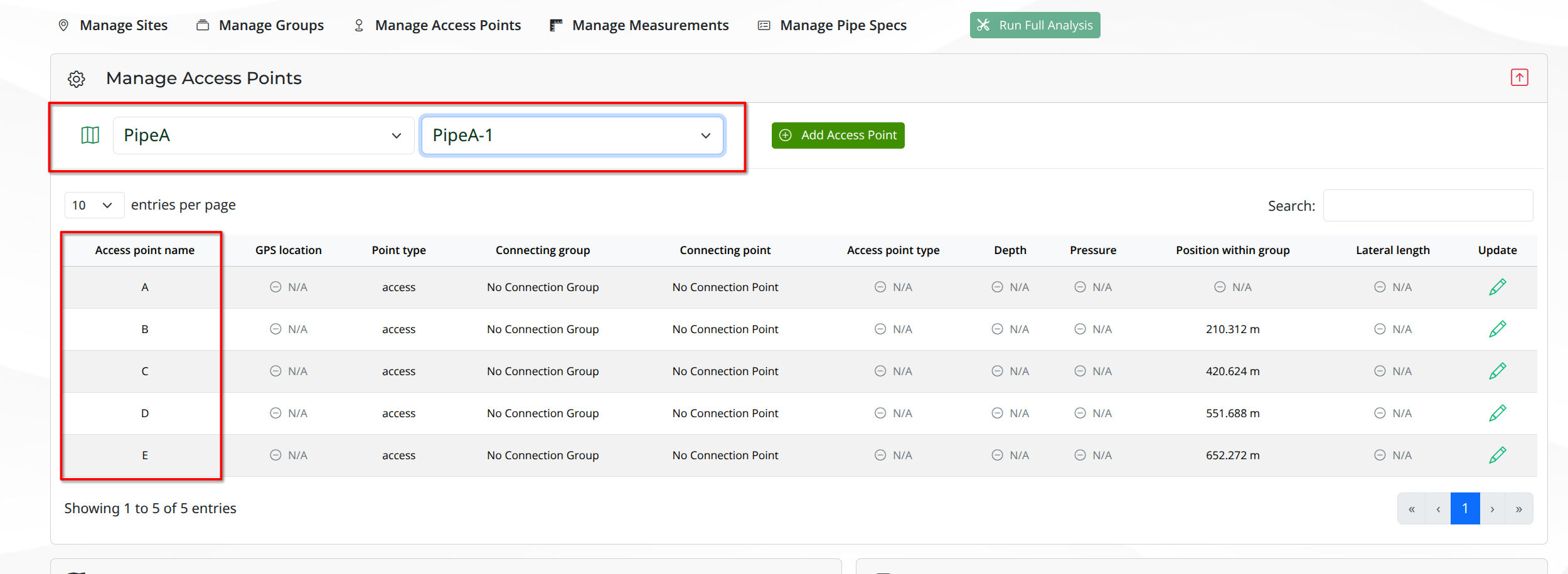
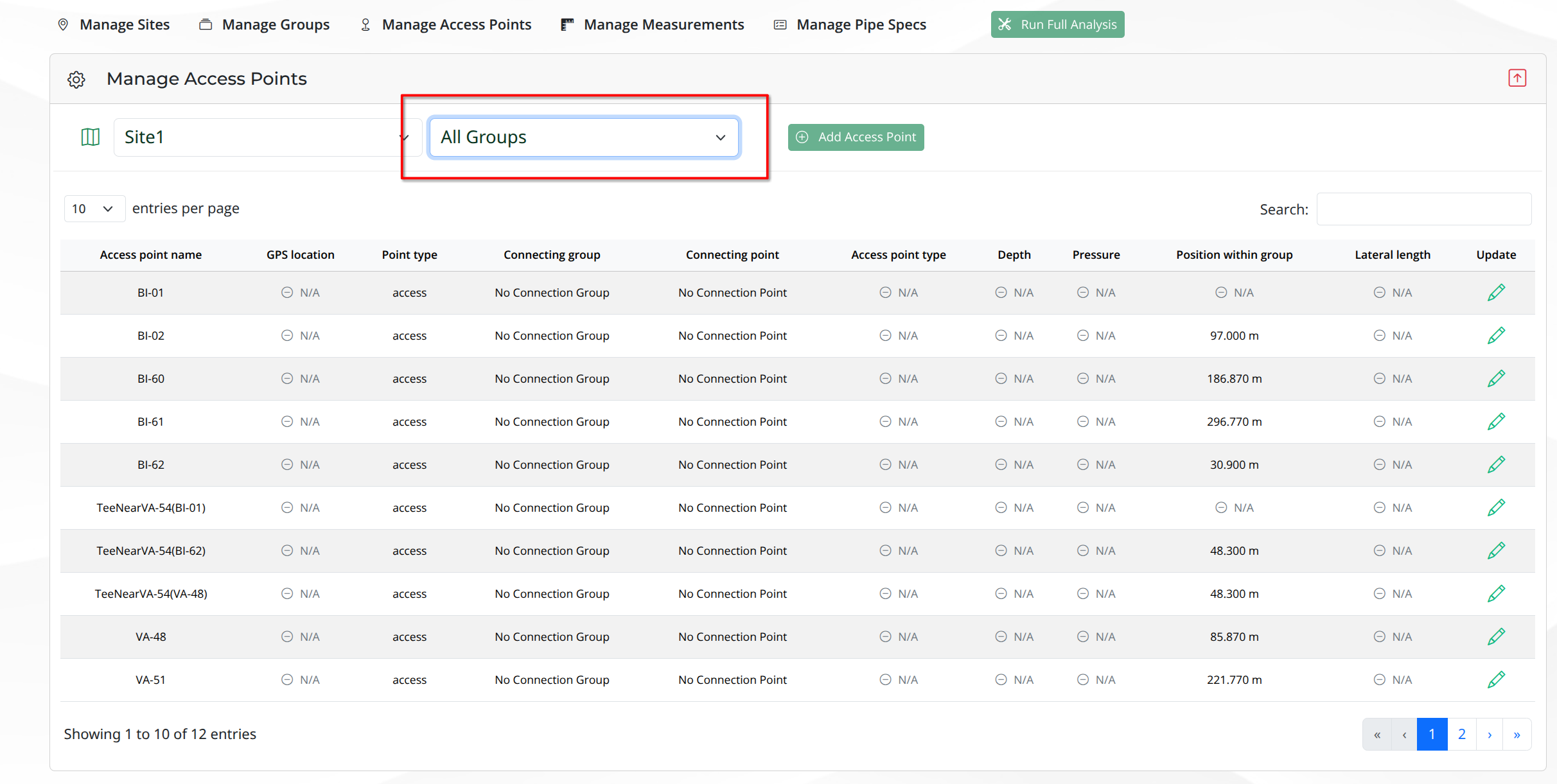
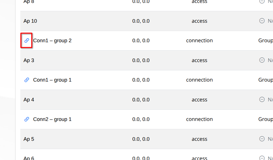
If the name of an access point is preceded by the icon , it means that the access point is type connection. If the icon is not present, the access point is of type access. The figure below shows the icon for access point type connection, in addition to the information available on the column Point Type.
Add Access Point Form

Click on this button to add a new access point to the selected site and group. The Add Access Point modal window form will open as shown in the figure below.
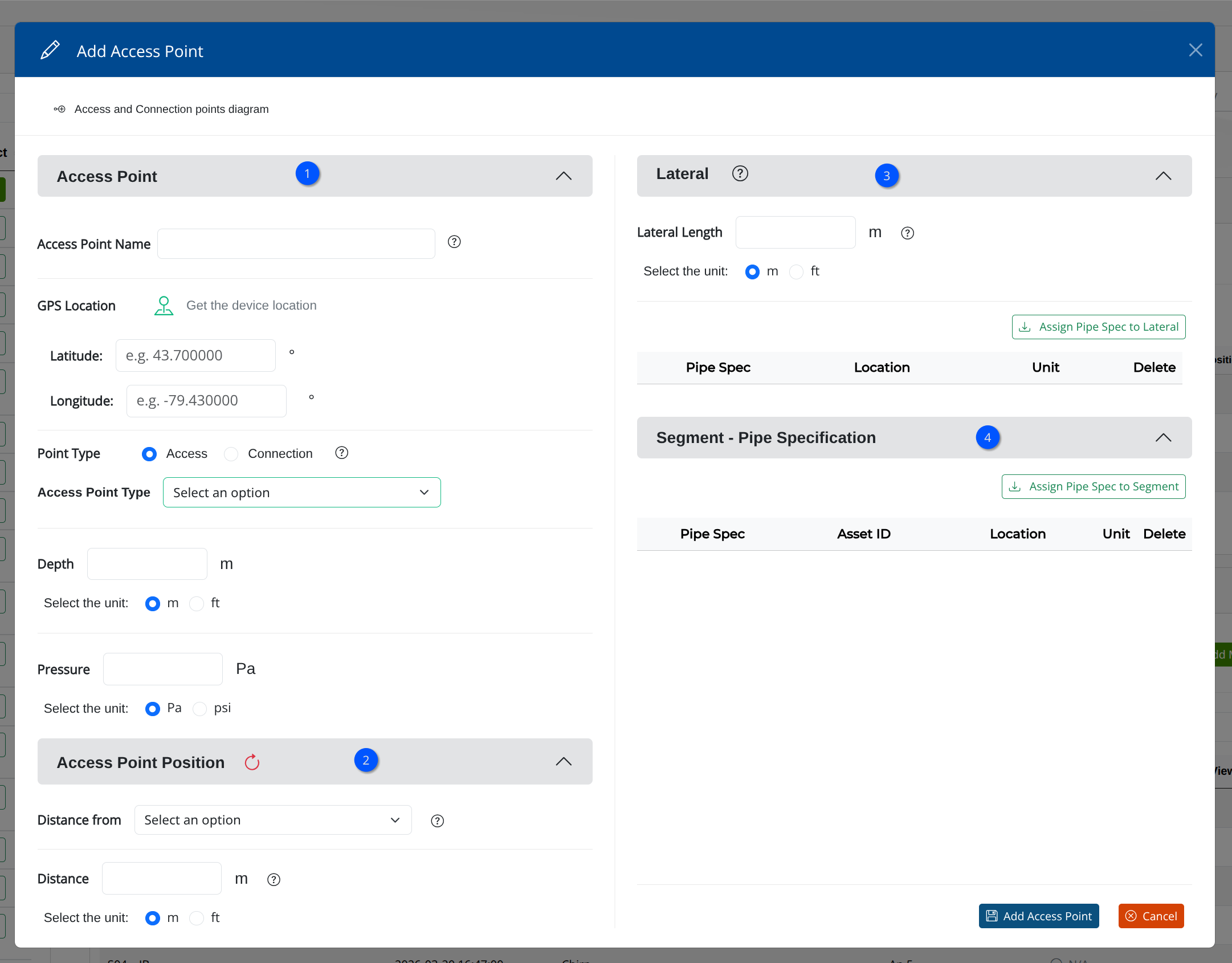
The Add Access Point form is divided into five sections:
Access Point
Access Point Position
Lateral
Segment - Pipe Specification
Access Point Section
The Access Point section contains the main fields related to the new access point information. It contains the following fields:
Access Point Name
This field is required. It is used to enter the name of the access point. The name of the access point must be unique within the project. If the user tries to create an access point with a name that already exists in the project, an error message will be displayed. Moreover, the name of the access point cannot be empty and only contain letters, numbers, spaces, and the following special characters: dashes (-) and underscores (_).
GPS Location
This field is optional. It is used to enter the GPS location of the access point. The GPS location must be in the format “latitude, longitude” (e.g., “40.7128, -74.0060”). If the user enters an invalid GPS location, or an invalid characater, an error message will be displayed.
Point Type
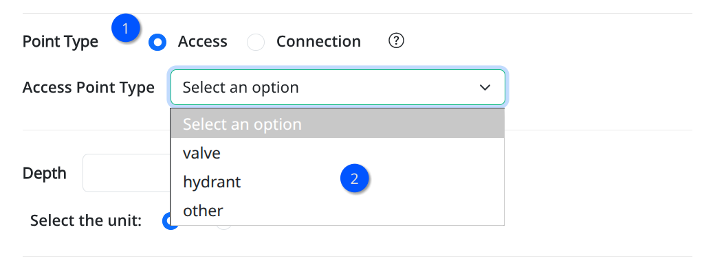
The Point Type field is required. It is used to select the type of the access point. The user can select either Access or Connection as the point type. The default value of this field is Access which can be one of the three types below:
valve
hydrant
other access point types that are not valve or hydrant
The figure below shows the dropdown list of the Access point type field with the available options.
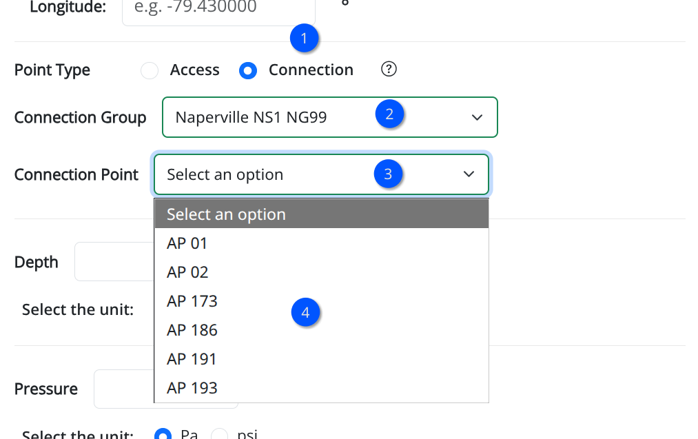
If the user selects Connection, an two dropdown lists will be displayed, which allows the user to select an existing access point to connect to:
Connection Group: This dropdown list allows the user to select the group of the access point to connect to. It is populated with the groups of the selected site, except the group of the current access point.
Connection Access Point: This dropdown list allows the user to select the access point to connect to. It is populated with the access points of the selected group on the Connection Group dropdown list.
The figure below shows the dropdown lists of the Connection point type field with the available options.
Depth
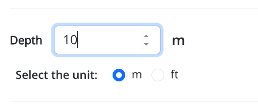
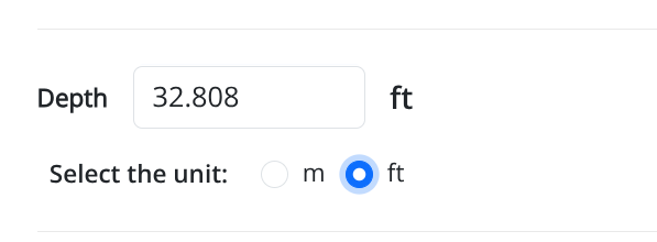
The field Depth is optional, and it is used to enter the depth of the access point in meters or feet. Depth is the vertical distance from ground level to the sensor / wave generator location.
The figure below displays the numeric field to enter the depth value, in addition to the radio buttons meter selected.
Pressure
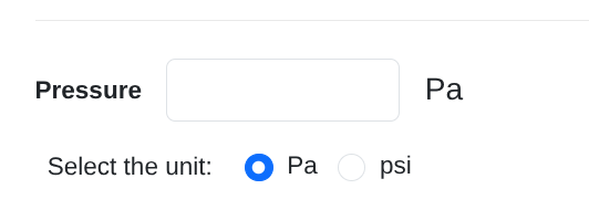
The field Pressure is optional, and it is used to enter the pressure of the access point in pascals or psi, representing the pressure of the fluid in the pipe at or near the access point location.
The figure below displays the numeric field to enter the pressure value, in addition to the radio buttons for the selected unit.
Access Point Position Section
The Access Point Position section contains fields related to the position of the access point. It contains the following fields:
Distance From
Distance
Distance From
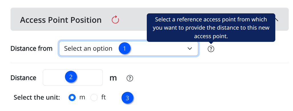
To position the new access point, select the reference point from the dropdown list of the field Distance From. The dropdown list contains all access points of the selected site, except the current access point being created.
Distance
After selecting the Distance From access point as reference, enter the distance value in meters or feet in the field Distance. The distance value is the distance from the reference point to the new access point.
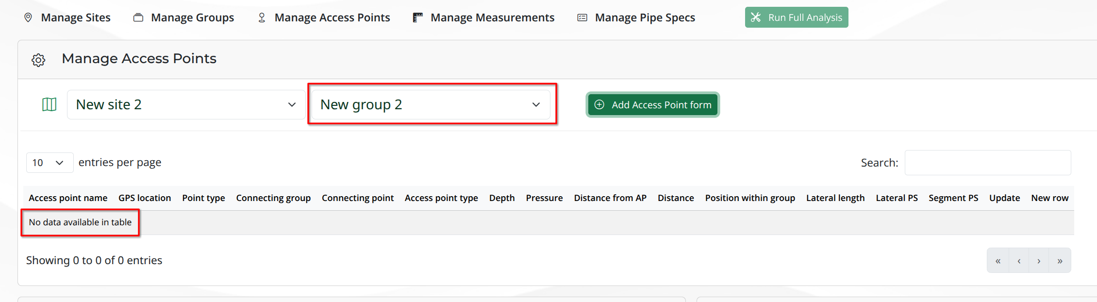
It’s important to note that, before the creation of the first access point in the group, the fields of the section Access Point Position are disabled. This is because the position of the first access point in the group is considered as the reference point for positioning the other access points in the same group. Therefore, the user can only enter the position information for the access points after creating the first access point in the group.
In the example below, the New group 2 is selected on the groups dropdown list, and the user is creating the first access point in this group. Therefore, the fields of the section Access Point Position are disabled.
When creating the first access point in a group, the alert below is displayed, and the section will be disabled. This first access point will have its position as zero.
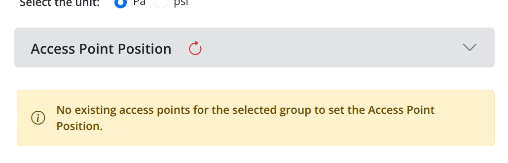
After creating the first access point in the group, which will have position zero, the section Access Point Position will be enabled for the other access points in the same group, and the user can enter the position information for these access points.
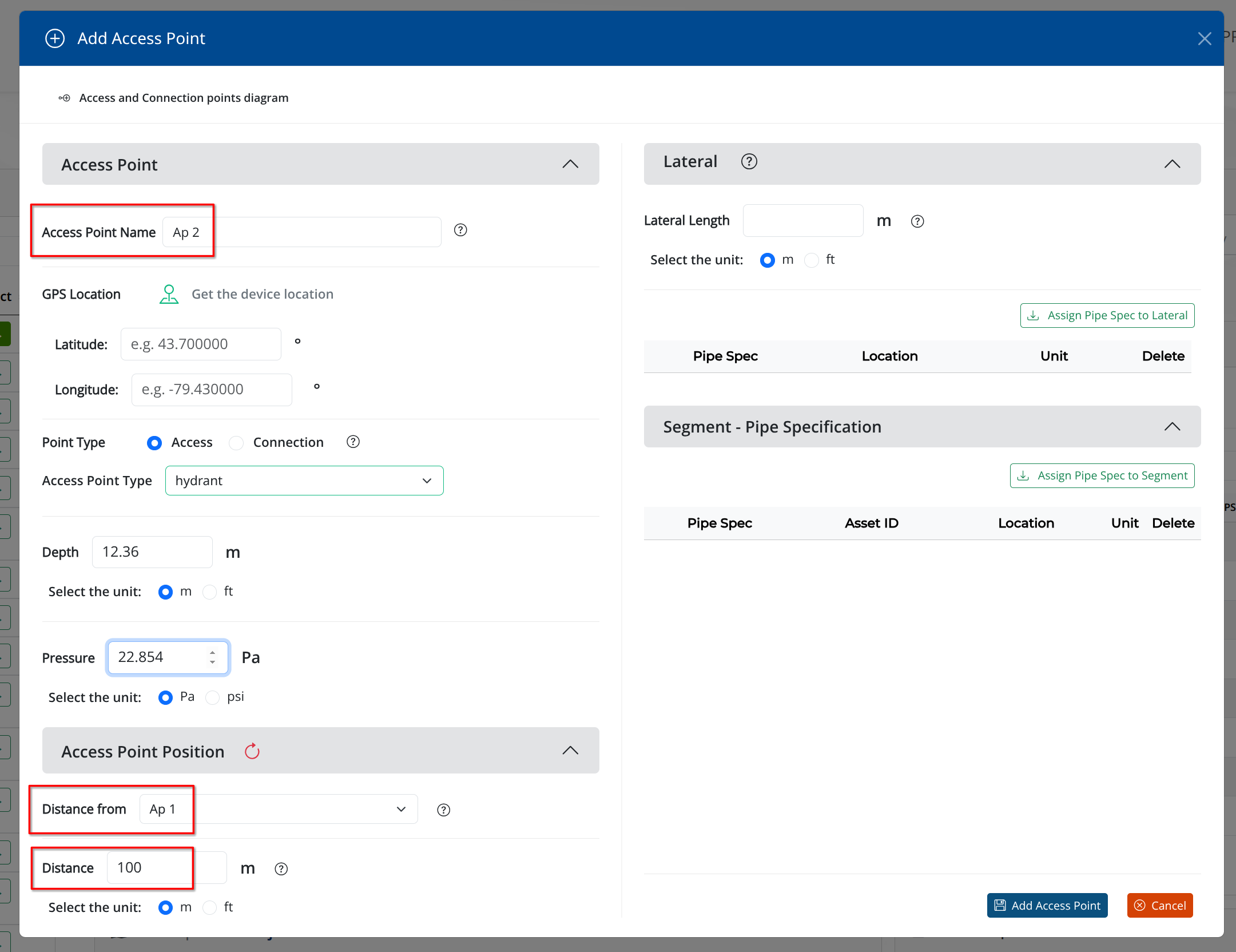
In the example below, the new access point Ap 2 is being created in the same group of the access point Ap 1, which is the first access point created in the group and has position zero. Ap 2 is located at a distance of 100 meters from Ap 1.
The figure below shows the form for the creation of Ap 2 at 100 meters from Ap 1.
After creating the new access point, the user can check its creation on the Manage Access Points table, and see the position information entered for this access point, like in the example below where Ap 2 is located at a distance of 100 meters from Ap 1.
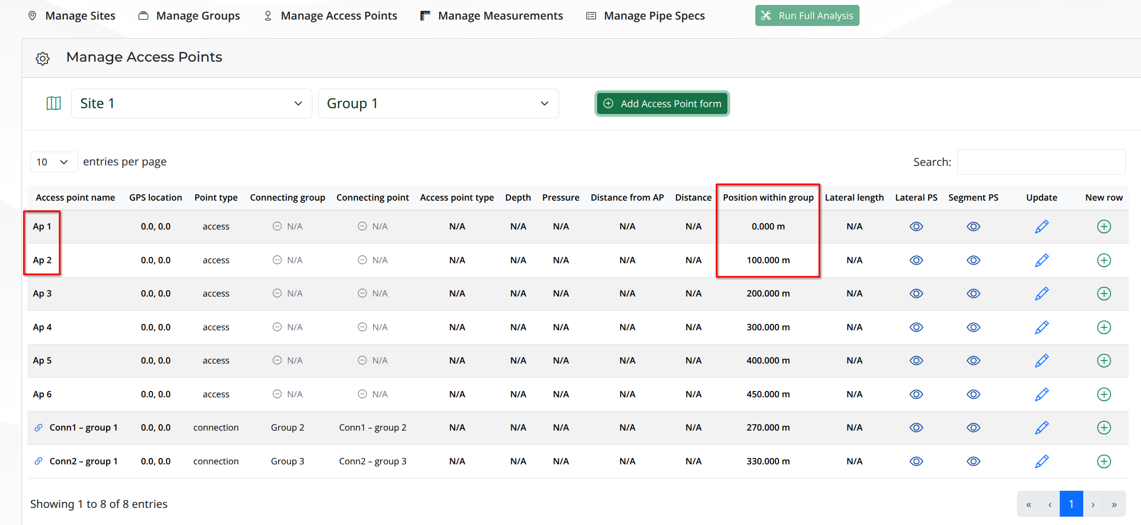
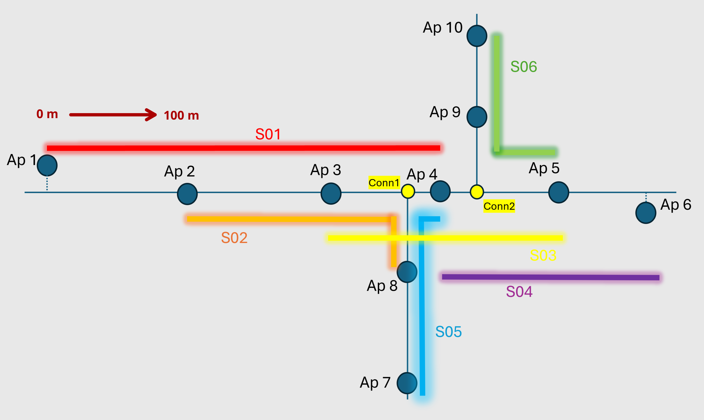
Observe in the table above that the Ap 3 was created at a distance of 100 meters from Ap 2. As a result, its Position within group is 200 meters, which is the distance from the reference point Ap 1 to Ap 3.
This is because Ap 2 is located at a distance of 100 meters from Ap 1, and Ap 3 is located at a distance of 100 meters from Ap 2. Therefore, the total distance from Ap 1 to Ap 3 is 200 meters, which is the value displayed in the column Position within group for Ap 3.
The same happened with Ap 4 and Ap 5, created at the distance of 100 meters from each other. In the case of Ap 6, it was created at a distance of 50 meters from Ap 5, which is located at a distance of 100 meters from Ap 4. Therefore, the total distance from Ap 1 to Ap 6 is 450 meters, which is the value displayed in the column Position within group for Ap 6.
The figure below shows the refresh icon on the Access Point Position section.

Lateral Section
A Lateral is an additional portion of pipe that is used to reach the pipe under assessment. No DRI results will be provided along the laterals. The Lateral section has the following fields:
Lateral Length
- Lateral Pipe Specifications table, which contains the following columns:
Lateral Spec
Lateral Spec Start Location
Units
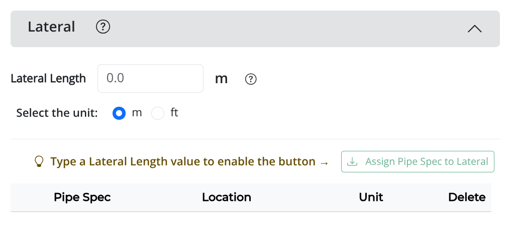
The figure below shows the Lateral section.
Lateral Length
After typing the lateral length value, select the unit for the lateral length from the radio buttons below the field. The default unit is meters. If the user selects feet as the unit, the value entered in the numeric field will be automatically converted to feet and displayed in the field.
Lateral Pipe Specifications Table
After clicking on the Assign Pipe Spec to Lateral button, the Add Lateral Pipe Specification window will be displayed with a form to assign a pipe specification to the lateral, as shown in the figure below.
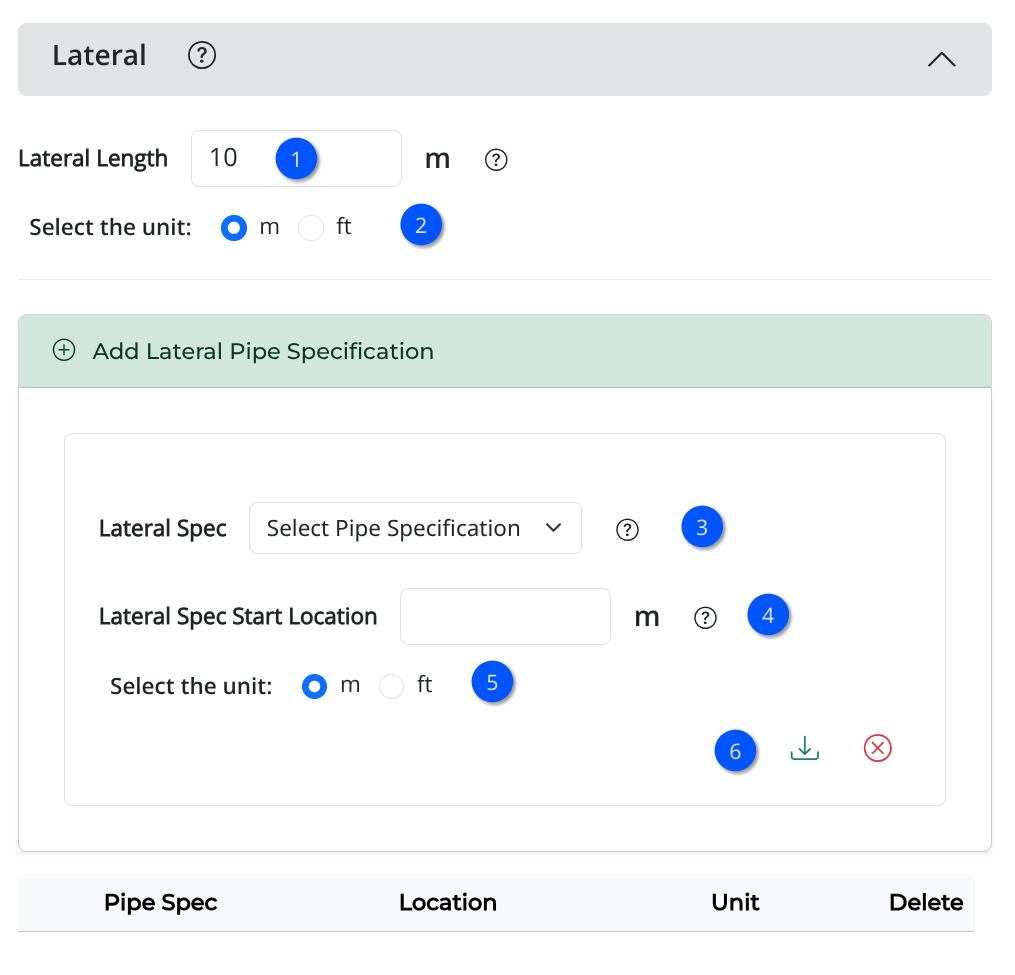
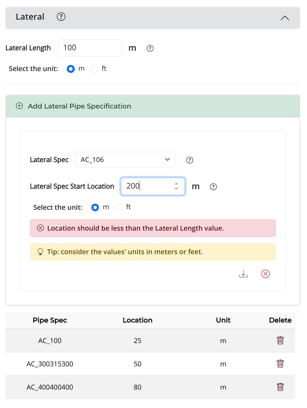
Initially, the table of the lateral pipe specifications is empty. To add a pipe specification to the table, the user should select a pipe specification from the dropdown list on the Lateral Spec dropdown list, type distance in the Distance field, select the unit in meters or feet, and click on the icon to add the selected pipe specification to the lateral.
The user can repeat this process to add more pipe specifications to the lateral. After adding the desired pipe specifications, click on the icon to close the form window, keeping only the added pipe specifications in the table.
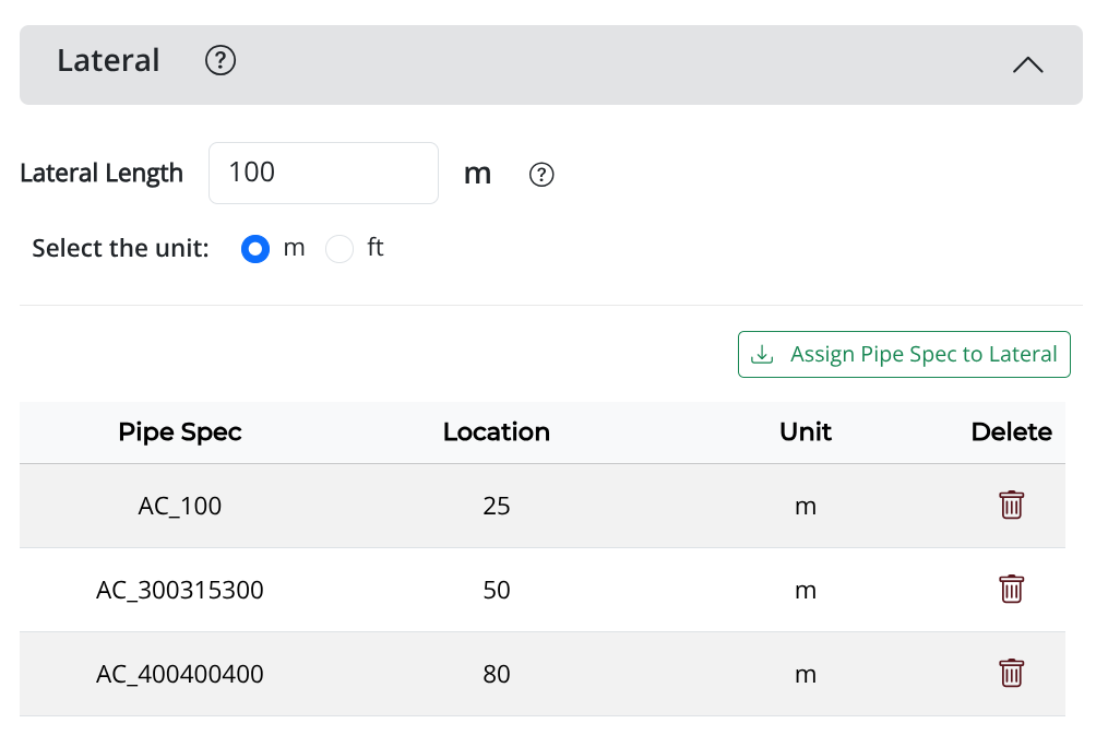
The figure below shows an example of the lateral pipe specifications table.
Segment - Pipe Specification Section
The section Segment - Pipe Specification contains fields related to the segment of the pipe under assessment and the pipe specifications assigned to this segment. It contains the following fields:
Pipe Spec → A dropdown list to select a pipe specification to assign to the segment of the pipe under assessment related to the access point being created.
Pipe Asset ID → A text field to enter the asset ID of the pipe segment under assessment related to the access point being created.
Spec Start Location → A numeric field to enter the start location of the pipe specification on the segment of the pipe under assessment related to the access point being created, in meters or feet.
The figure below displays the section Segment - Pipe Specification of the form.
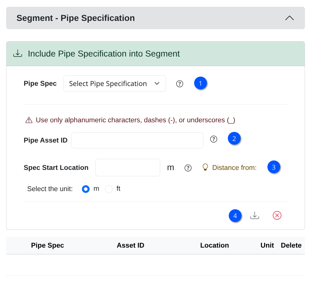
The window allows the user to assign a pipe specification to the segment of the pipe under assessment related to the access point being created.
To start assigning a pipe specification, select a pipe specification from the dropdown list 1. Then, enter the asset ID of the pipe segment under assessment in the field Pipe Asset ID 2.
Next, type the start location of the pipe specification on the segment of the pipe under assessment in the field Spec Start Location3, select the unit for the start location in meters or feet, and click on the icon to add the selected pipe specification to the segment table4.
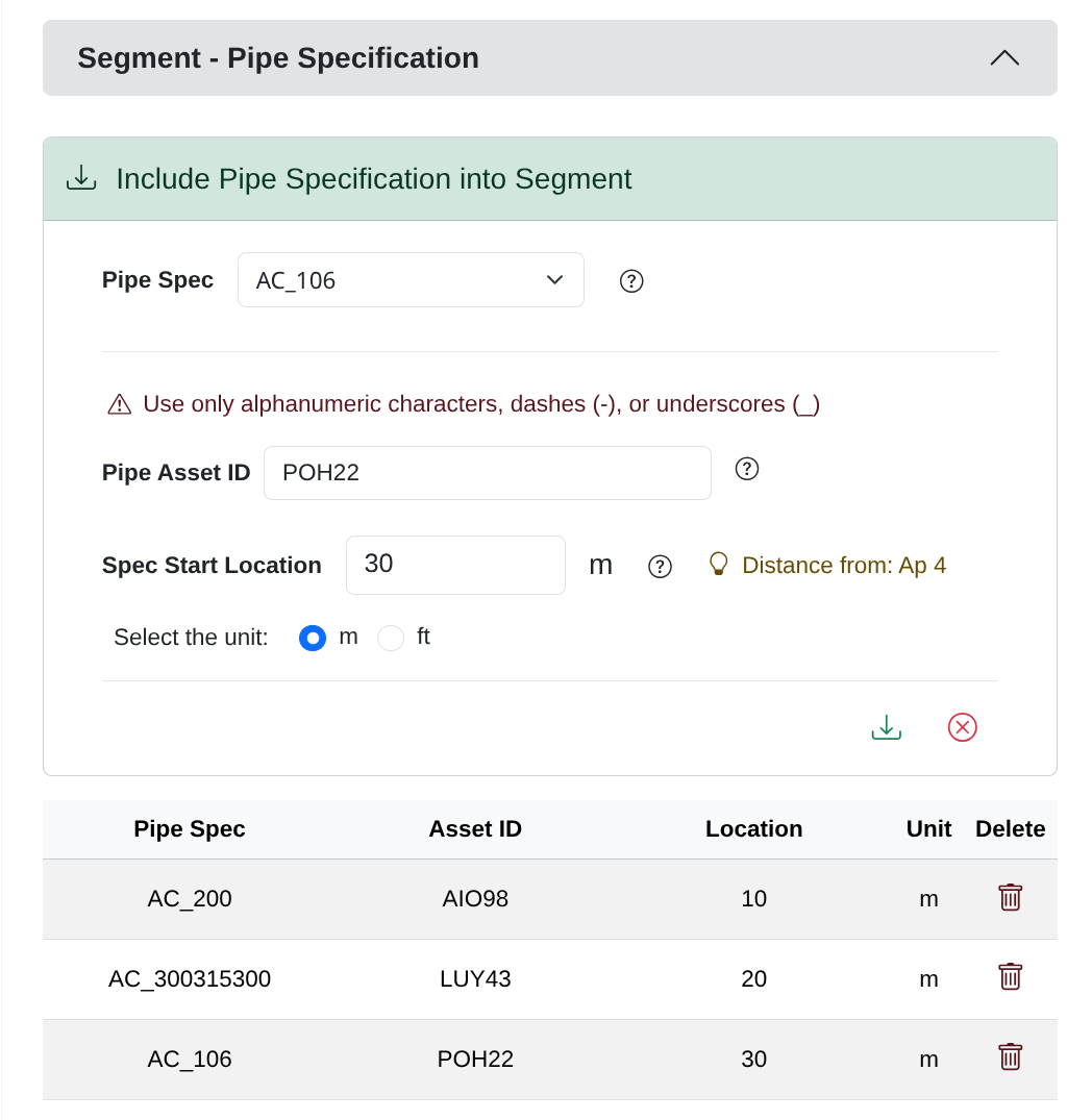
The figure below shows an example of the section Segment - Pipe Specification filled with the pipe specification assigned to the segment of the pipe under assessment related to the access point being created.
Distance From Label
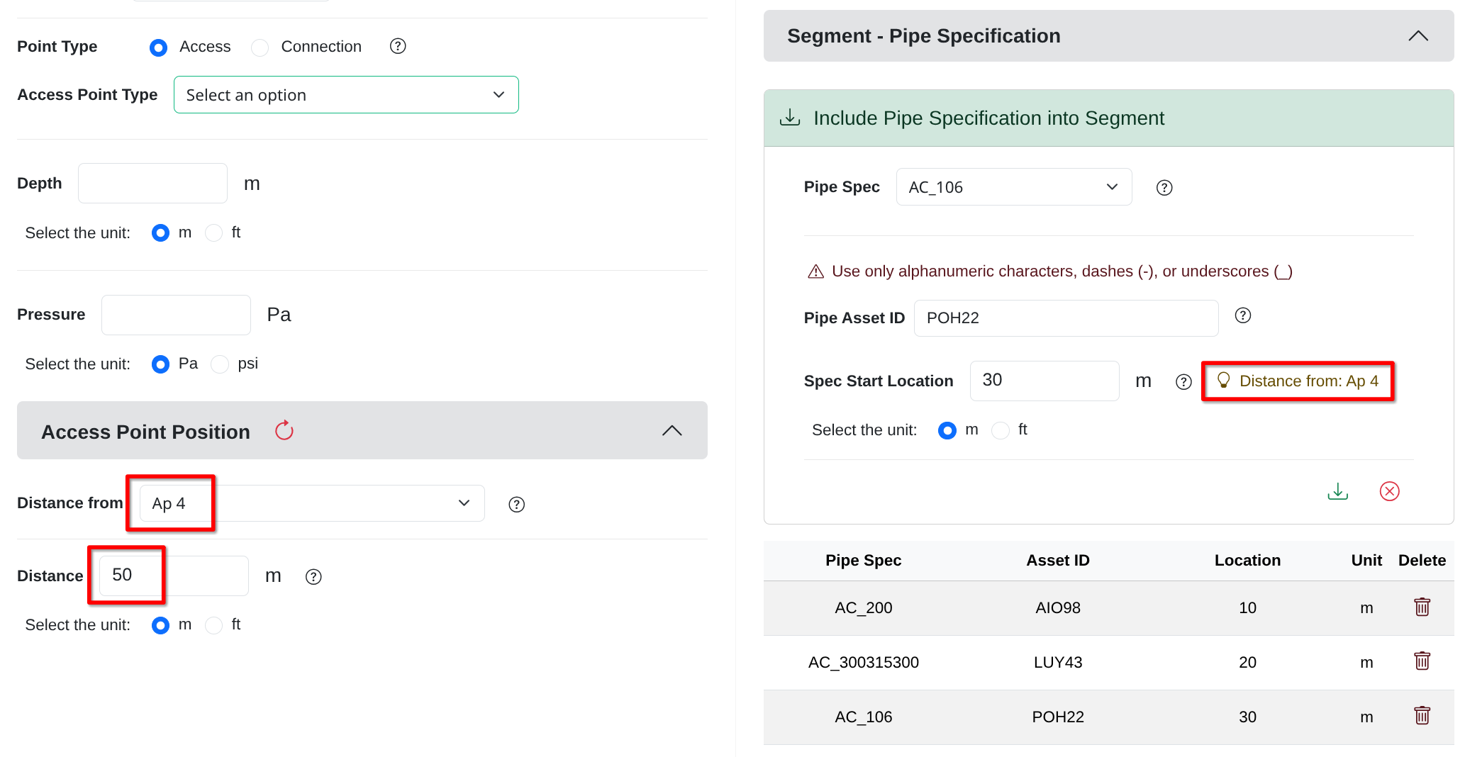
Beside the field Spec Start Location there is a label that shows the name of the access point selected as reference in the Distance From dropdown list, and its distance from the reference point. This label is updated based on the access point selected as reference in the dropdown list, and it helps the user to know the name and position of the reference access point when entering the position information for the new access point.
The figure below shows the label with the name and distance of the reference access point.
Access Point Graph
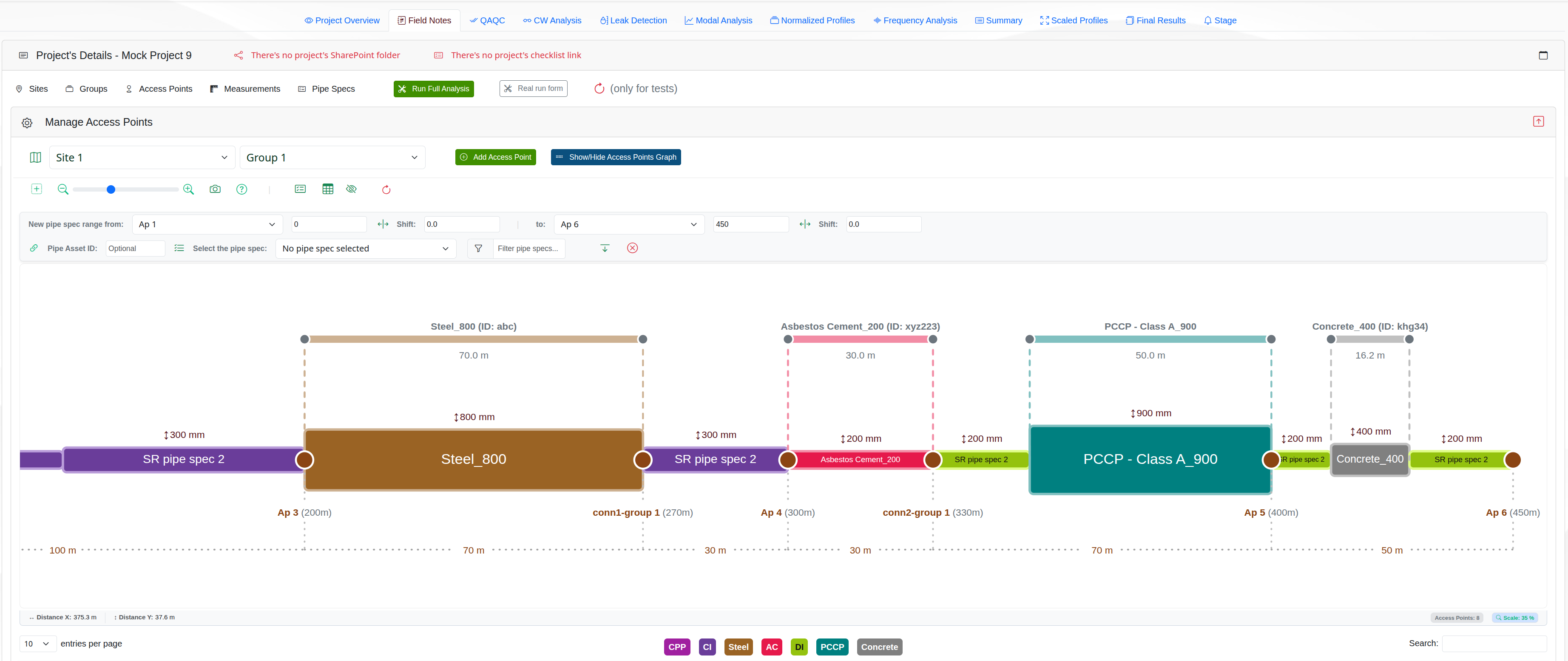
The Access Point Graph panel provides a visual representation of the pipe with its access points and pipe specifications (pipe specs) for the selected site and group. It is displayed above the Manage Access Points table and is hidden by default.
When the graph is shown, it is refreshed for the current site and group selection. The panel is rendered in a wide container so the graph can use the available space and keep the access point layout readable.
The graph helps the user inspect the selected group in a visual way:
Each access point is shown as a labeled brown circled marker on the pipe line.
The distance between access points is displayed directly on the graph.
The pipe sections are drawn with colors that match the pipe material family.
Any pipe specification added to the graph is displayed as an overlay above the pipe line.
It’s possible to create, update, and delete pipe spec sections independently from the pipe sections.
A badge legend below the graph shows the pipe materials included in the current view.
The figure below shows an example of a pipe with all its graph components.
Graph controls
The toolbar above the graph contains the controls used to navigate and work with the diagram.

From left to right and below, the graph controls are:
- Center graph - restores the graph to its default position and zoom.
- Zoom in / Zoom out - changes the graph scale. The user can also use the mouse wheel over the graph if it's available.
- Zoom slider - lets the user adjust the graph scale manually. Double-clicking the slider resets the whole graph to the center.
- Export image - downloads the current graph as a high-resolution PNG image.
- Help - opens a short description of the available graph controls.
- Pipe Specification Controls - opens/closes the panel used to add or update pipe specification sections on the graph.
- Pipe Specification Table - opens/closes the table with pipe specs information from and to distances, including the user changes.
- View New Pipe Specs - shows/hides only the pipe specifications added by the user on the graph, hiding the original pipe sections.
- Reset Pipe Specs - resets the pipe specifications on the graph to the original values, removing any user changes.
The graph canvas also supports keyboard and mouse navigation:
Hold the Space bar and drag the mouse to pan the graph.
Use the Arrow keys to move the graph.
Hovering the graph updates the pointer position on the status bar used by the zoom controls.
The graph canvas also supports keyboard and mouse navigation:
- Hold the Space bar and drag the mouse to pan the graph.
- Use the Arrow keys to move the graph.
- Hovering the graph updates the pointer position on the status bar used by the zoom controls.
To see a brief description of the graph controls, click on the Help button on the graph toolbar. The help panel will be displayed with a short description of the available graph controls.
Pipe Specs controls
The Pipe Specs Controls panel allows the user to add, edit, and delete pipe specifications on the graph. The user can also view the pipe specifications table with the from and to distances of the pipe specifications, including any changes made by the user.

The Pipe Specs Controls panel contains the following controls:
- New pipe spec range - lets the user choose the starting and ending access points and enter the from/to distances, with shift values for each side of the range.
- Shift - adds or subtracts the value entered in the number field to the From and To distances.
- Pipe Asset ID - optional field to enter the pipe asset identifier for the selected range.
- Select the pipe spec - dropdown used to choose the pipe specification to apply to the selected range.
- Filter pipe specs - filters the pipe specification list before selection.
- Add pipe spec - applies the selected pipe specification to the chosen range.
- Close - closes the panel without applying further changes.
The figure below shows a typical pipe graph example and some pipe specifications created using the Pipe Specs Controls panel.
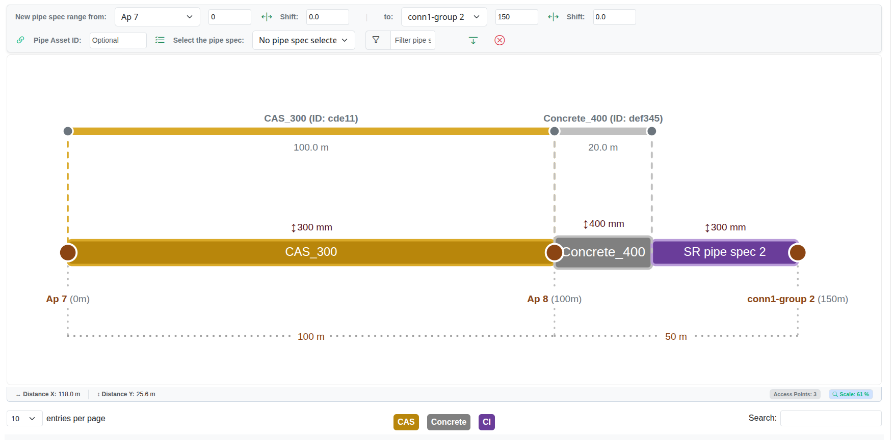
The whole graph has two main sections:
Pipe Graph - shows the pipe with its access points and pipe specifications sections, and
Pipe specifications - shows the pipe specifications created or edited by the user with the Pipe Specs Controls.
The Pipe Graph section is the main section of the graph, and it shows the pipe with its access points and pipe specifications sections.
The Pipe Specifications section is the section above the Pipe Graph section that shows the pipe specifications created or edited by the user with the Pipe Specs Controls.
The Pipe Specifications section override the pipe specifications of the Pipe Graph section.
Creating a New Pipe Specification
The Pipe Specs Controls panel allows the user to add, edit, and delete pipe specifications on the graph. The user can also view the pipe specifications table with the from and to distances of the pipe specifications, including any changes made by the user.
To create a new pipe specification, use the controls below in order.
- New pipe spec range from - select the starting access point and enter the From distance.
- Shift - optional control that adds or subtracts the value in the number field to shift the range left or right.
- To - select the ending access point and enter the To distance.
- Shift - optional control that adds or subtracts the value in the number field to shift the range left or right.
- Pipe Asset ID - optional field to enter the pipe asset identifier for the selected pipe specification.
- Select the pipe spec - choose the pipe specification to apply to the selected range.
- Filter pipe specs - filters the available pipe specifications before selection.
- Add pipe spec - applies the selected pipe specification to the new range.
Close - closes the panel without adding a new pipe specification.
Updating a Pipe Specification
To update an already created new pipe specification, click on one of the pipe specification sections on the graph and select the option Update from the context menu.
The pipe specification will populate the Pipe Specs Controls panel for editing.
Make the changes and click again on the icon Add pipe spec to update the pipe specification on the graph.

After clicking on the Add Pipe Spec button, the pipe spec will be added to the Pipe Specification Sections of the graph. If there were affected pipe specifications, they will be updated accordingly. The user can see the changes in the Pipe Specification Sections of the graph.
Deleting a Pipe Specification
To delete an already created new pipe specification on the graph, click on one of the pipe specification sections on the graph and select the option Delete from the context menu.
A confirmation window will be presented to the user to confirm or cancel the action.
After deleting the pipe spec section, the pipe section(s) will be updated with the original pipe specifications.